Futaba 10C 2.4GHz Manuel d'utilisateur
Naviguer en ligne ou télécharger Manuel d'utilisateur pour Accessoires de communication Futaba 10C 2.4GHz. Futaba 10C 2.4GHz User Manual Manuel d'utilisatio
- Page / 119
- Table des matières
- MARQUE LIVRES
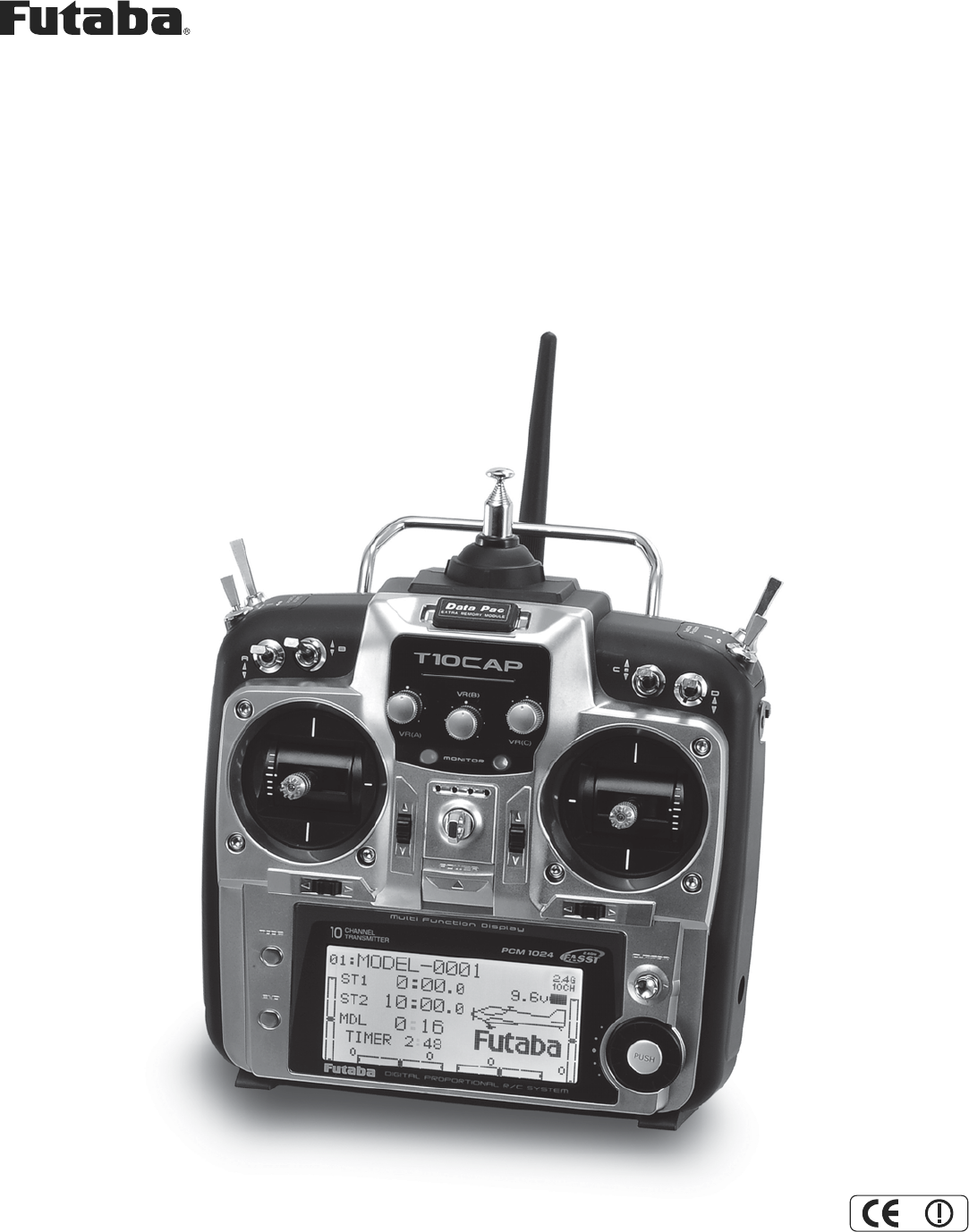
- 10CAP/10CHP/10CP 1
- TRANSMITTER CONTROLS - HELI 12
- 120˚120˚ 15
- Stick tip A Locking piece B 16
- Antenna Antenna 19
- ACRO Basic Menu 26
- LOGIC SW 63
- : See p. 38 63
- To create an 68
- [Note screen reads 77
- GLID (2A+2F) 83
- START DELAY 85
- trims ( 85
- Adjustability: 102
- , again.) 103
- 50%0% +100% 107
- CVA%001%0RON%001 107
- GV-1 connections 108
- THROTTLE STICK 114
- Programmable mix 115
Résumé du contenu
10CAP/10CHP/10CP10-CHANNEL RADIO CONTROL SYSTEM INSTRUCTION MANUALTechnical updates and additional programming examples available at: http://www.futab
10The following additional accessories are available from your dealer. Refer to a Futaba catalog for more information: • CAMPac0HPRU\ PRGXOH WKH
100THR-CURVE and PIT-CURVE: These 7-point curves are utilized to best match the blade collective pitch to the engine RPM for consistent load on the en
101Revo. mixing rates are 5-point curves. For a clockwise-turning rotor, the rudder is mixed in the clockwise direction when collective pitch is incre
102OFFSET: Optional separate trims in addition to those for the normal condition. This function is used to automatically change WKH WULP RI D KHOL
103DELAY: The Delay function provides a smooth transition between the trim positions whenever OFFSET,REVO. MIXING, or THROTTLE HOLD functions are turn
104HOVERING ADJUSTMENTS (HOV-THR and HOV-PIT):+RYHULQJWKURWWOHDQGKRYHULQJSLWFKDUH¿QHWXQLQJDGMXVWPHQWVIRUWKHWKURWWOHDQGFROOHFWLYHSLWFKFX
105HIGH/LOW PITCH (HI/LO-PIT):7KLVIXQFWLRQPD\EHXVHGWRDGMXVWWKHFXUYHVKLJKDQGORZVLGHLQGLYLGXDOO\IRUHDFKÀLJKWFRQGLWLRQQRUPDOLGOHXS
106*<526DQG*29(512568VLQJHOHFWURQLFVWRWDNHVRPHRIWKHFRPSOH[LW\RXWRIVHWXSVDQGÀLJKWWhat is a gyro? A gyroscope is an electronic unit
107Gain Example for AVCS/Heading-hold Gyros (GY)GOAL of EXAMPLE: STEPS: INPUTS:6HWXSDKHDGLQJKROG$9&6J\URZLWKKHDGLQJKROG$9&6VHWWLQJ
108GOVERNORS:What is a governor? A governor is made up of a set of sensors which read the RPM of the helicopter’s head, and a control unit that automa
109The GV-1 controls throttle when it is active, so the throttle will not obey any FailSafe settings preset for throttle in the WUDQVPLWWHU$OZD\VVH
117KLV¿JXUHVKRZVWKHGHIDXOWVZLWFKDVVLJQPHQWVIRUD&$0RGHV\VWHPDVVXSSOLHGE\WKHIDFWRU\You can change many of the switch positions
110GLOSSARY '&RPPRQQDPHIRUFHUWDLQW\SHVRIDHUREDWLFPDQHXYHUV$LUFUDIWÀ\LQJEHORZWKHPRGHO¶VVWDOOVSHHGVXFKDVWRUTXHrolls. He
111triggered by THROTTLE STICK POSITION. For similar glider programming, see BUTTERFLY... 63 $0$$FDGHP\RI0RGHO
112servos.&KDQQHOVZLWFKVHOHFWLRQDQGGLUHFWLRQFRQWURO6HHAUX-CH...
113Elevator: surface which controls the model’s rate of climb or descent. Also called cyclic pitch on helicopters.Elevator-to-airbrake mix: (GLID) use
114FUNC: function mode of TRAINER, allows student radio to use the computer programming for that channel in the master UDGLR ([ DOORZV D VWXGHQW
115,QÀLJKWQHHGOHFRQWUROVHHTHROTTLE-NEEDLE.INHPDNHVDIHDWXUHLQDFWLYHXQDEOHWREHXVHG:KHQDIXQFWLRQLVLQKLELWHGLWFDQQRWEHXVHGHYHQ
116VHWXSVLPLODUPRGHOVRUPDNHDFRS\RIDZRUNLQJPRGHOWRH[SHULPHQWZLWKQHZVHWXSV$OVRXVHGWRFRS\PRGHOVWRfrom the CAMpac data storage
117PITCH CURVE: (HELI FXUYH WKDW VHWV WKH UHVSRQVH RI WKH FROOHFWLYH SLWFK VHUYRV WR PRYHPHQW RI WKH WKURWWOHFROOHFWLYHSTICK ,QG
118switch. 10C of fers 4 separate snaps with 1 or 2 switches used for selection. ...
119Throttle trim adjustment: see ATL to change throttle trim from “idle only” to full trim control like all other channels. See THR-REV to reverse THR
127KLV¿JXUHVKRZVWKHGHIDXOWVZLWFKDVVLJQPHQWVIRUD&+0RGHV\VWHPDVVXSSOLHGE\WKHIDFWRU\You can change many of the switch positions
13NOTE: If you need to remove or replace the transmitter battery, do not pull on its wires to remove it. Instead, JHQWO\SXOORQ WKH FRQQHFWRUV SO
14RECEIVER AND SERVO CONNECTIONSReceiverOutput andChannelAircraft (ACRO)1 DLOHURQVDLOHURQ1FRPELQHGÀDSDLOHURQ22 elevator3 throttle4 rudder5
15The initial charge, and any charge after a complete discharge, should be at least 18 hours to ensure full charge. The batteries should be left RQFK
16Adjusting the length of the non-slip control sticks <RXPD\DGMXVWWKHWHQVLRQRI\RXUVWLFNVWRSURYLGHWKHIHHOWKDW\RXSUHIHUIRUÀ\LQJ7RD
17Changing Modes (TX SETTING):Hold down MODE and END keys while turning on the transmitter to call TX SETTING menu. Stick Mode: The screen reads "
18RADIO INSTALLATION Follow these guidelines to properly mount the servos, receiver and battery. • Make certain the alignment tab on the battery, swit
19• When you install the switch harness to the helicopter, please use the switch cover. Generally sandwich the frame by switch and switch cover and se
2TABLE OF CONTENTSINTRODUCTION ... 3Additional Technical Help, Support and Service ...
20• The receiver contains precision electronic parts. It is the most delicate radio component on-board the model and should EHSURWHFWHGIURPYLEUDWLR
217UDQVPLWWHUV$QWHQQD70PRGXOHRQO\1. The transmitter antenna is adjustable so please make sure that the antenna is never SRLQWHGGLUHFWO\DW
2272 MHz bandCh. MHz Ch. MHz11 72.010 36 72.51012 72.03037 72.53013 72.050 38 72.55014 72.070 39 72.57015 72.090 40 72.59016 72.110 41 72.61017 72.130
23TRANSMITTER DISPLAYS & BUTTONS :KHQ\RX¿UVWWXUQRQ\RXUWUDQVPLWWHUDFRQ¿UPDWLRQGRXEOHEHHSVRXQGVDQGWKHVFUHHQVKRZQEHORZDSSHDUV%HI
24WARNING & ERROR DISPLAYS An alarm or error indication may appear on the display of your transmitter for several reasons, including when the tran
25AIRCRAFT (ACRO) MENU FUNCTIONS Please note that all BASIC menu functions are the same for airplanes (ACRO), sailplanes (GLID), and helicopters (HELI
26MAP OF ACRO BASIC FUNCTIONS ACRO Basic Menu( for one second)(Startup screen)(Basic Menu 1/2)To return to the Startup screen, press the End key.(Basi
27A QUICK GUIDE: GETTING STARTED WITH A BASIC 4-CHANNEL AIRCRAFTThis guide is intended to help you get acquainted with the radio, to give you a jump s
28With digital trims you don’t shut the engine off with THROTTLE TRIM. Let's set up IDLE-DOWN and "throttle cut" (THR-CUT)now. GOALS of
29GOALS of EXAMPLE STEPS INPUTS for EXAMPLE Set the second (low) rate throws and exponential.A to down position.CtoD/R.Repeat steps above to set low
3INTRODUCTIONThank you for purchasing a Futaba®&VHULHVGLJLWDOSURSRUWLRQDO5&V\VWHP)$667*+]* or PCM1024 system). This system is e
30$/22.$77+(5$',26)81&7,21667(3%<67(3MODELsubmenu: includes three functions that manage model memory: MODEL SELECT,MODELCOPY and
31MODEL COPYFRSLHVWKHFXUUHQWPRGHOGDWDLQWRDQRWKHUPRGHOPHPRU\LQWKHWUDQVPLWWHURUWKHRSWLRQDO'3..128KCAMPac). The name of the
32MODEL NAME: assigns a name to the current model memory. By giving each model a name that is immediately recognizable, \RXFDQTXLFNO\VHOHFWWKHFRU
33PARAMETERsubmenu: sets those parameters you would likely set once, and then not disturb again. Once you have selected the correct model you wish to
34MODEL TYPE: sets the type of programming used for this model.The T10C has 15 model memories, which can each support:•one powered aircraft (ACROPHP
35Modulation select (MODUL): sets the type of modulation transmitted.The modulation of your receiver will determine whether you utilize FM (PPMPCM o
36Adjustable travel limit (ATL): makes the channel 3 TRIM LEVER (THROTTLE TRIM) effective only at low throttle, disabling the trim at high throttle. T
37Home screen display mode selection (HOME-DISP) (HELI only): selects the display item in the home screen for HELI.ILLUST: displays the illustration o
38Servo reversing (REVERSE): changes the direction an individual servo responds to a CONTROL STICK motion. [Since channel 9 and 10 are switch only (an
39End Point of servo travel adjustment (END POINT, also called EPA): the most flexible version of travel adjustment available. It independently adjust
4$SSOLFDWLRQ([SRUWDQG0RGL¿FDWLRQ1. This product may be used for model airplane or surface (boat, car, robot) use, if on the correct frequency. I
40Engine idle management:IDLE-DOWN and THR-CUT: functions which work with the digital THROTTLE TRIM to provide a simple, consistent means of engine op
41Throttle cut (THR-CUT) (ACROHELISURYLGHV DQHDV\ ZD\ WRVWRS WKH HQJLQH E\ ÀLSSLQJD VZLWFK ZLWKTHROTTLE STICK at idle). The movement
42'XDOWULSOHUDWHVDQGH[SRQHQWLDOD/R,EXP): assigns adjusted rates and exponential. Dual/Triple Rates:UHGXFHLQFUHDVH WKHVHUYRWUDYHOE\IO
43Adjustability:• More sensitive around neutral. (positive exponential, see example) • Less sensitive around neutral. (negative exponential, see examp
44GOAL of EXAMPLE: STEPS: INPUTS:Set up aileron triple rates on SWITCHC with travel settings of 75% (normal), 25% (slow roll) and 140% (extreme aeroba
45TIMERsubmenu (stopwatch functions): controls three electronic clocks used to keep track of time remaining in a FRPSHWLWLRQWLPHDOORZHGÀ\LQJWLPH
46Auxiliary channel function (including channel 9-10 controls)(AUX-CHGH¿QHVWKHUHODWLRQVKLSEHWZHHQWKHWUDQVPLWWHUcontrols and the receiver outp
47TRAINER: for training novice pilots with optional trainer cord connecting 2 transmitters. The instructor has several levels of controllability. Adju
48TRIMsubmenu: resets and adjust effectiveness of digital trims. The 10C has digital trims which are different from conventional mechanical trim slide
49SUB-TRIM: makes small changes or corrections to the neutral position of each servo. Range is -120 to +120, with 0 setting, the default, being no SUB
5Meaning of Special Markings Pay special attention to safety where indicated by the following marks: DANGER3URFHGXUHVZKLFKPD\OHDGWRGDQJHURXVF
50FailSafe (loss of clean signal and low receiver battery) submenu (PCM2.4G mode only) (F/S): sets responses in case of loss of signal or low Rx batt
51ACRO ADVANCE MENU FUNCTIONS: Aircraft wing types (ACROGLID):There are 3 basic wing types in aircraft models: • Simple. Model uses one aileron servo
52UsingFLAPERON (ACROGLID 1A+1F ): The FLAPERONPL[LQJIXQFWLRQXVHVRQHVHUYRRQHDFKRIWKHWZRDLOHURQVDQGXVHVWKHPIRUERWKDLOHURQDQGÀDSIX
53UsingFLAP-TRIMFDPEHUWRDGMXVWÀDSHURQV (ACROGLID ) FLAP-TRIM assigns the primary flaperon control [defaults to VR(A)] to allow trimming in flig
54Using Aileron Differential (AILE-DIFF)(ACROGLID 2A+1FGLID 2A+2F):$LOHURQGLIIHUHQWLDOLVSULPDULO\XVHGRQRUVHUYRZLQJVZLWKRQHVHUYRVR
55Using Twin Aileron Servos with a 5-channel receiver, AILE-2 (ACROGLID ):AILE-2 allows FLAPERON and AIL-DIFF with a 5-channel receiver. AILE-2 only
56There are 4 basic tail types in aircraft models:• Simple. Model uses one elevator servo and one rudder servo (or multiple servos on a Y-harness). Th
57Dual Elevator Servos (with a rudder) (AILEVATOR) (ACRO): Many models use two elevator servos, plugged in separate receiver channels. (Flying wings w
58UsingV-TAIL (ACROGLID):V-TAIL mixing is used with v-tail aircraft so that both elevator and rudder functions are combined for the two tail surfaces
596QDS5ROOVDWWKHÀLFNRIDVZLWFKSNAP-ROLL) (ACRO):7KLVIXQFWLRQDOORZV\RXWRH[HFXWHVQDSUROOVE\ÀLSSLQJDVZLWFKSURYLGLQJthe same input e
6$WWKHÀ\LQJ¿HOGOther than 2.4GHz system: %HIRUHÀ\LQJEHVXUHWKDWWKHIUHTXHQF\\RXLQWHQGWRÀ\ZLWKLVQRWLQXVH and secure any frequency co
60GOAL of EXAMPLE: STEPS: INPUTS:Activate SNAP-ROLL. Adjust elevatortravel to 55%, rudder travel to 120%LQWKHULJKWXSVQDS$FWLYDWHSAFE-MOD so s
61MIXES: the backbone of nearly every functionMixes are special programs within the radio that command one or more channels to act together with input
62ELEV-FLAPmixing (ACROGLID):ELEV-FLAPPL[LQJLVWKH¿UVWSUHSURJUDPPHGPL[ZHOOFRYHU7KLVPL[PDNHVWKH ÀDSV GURS RU ULVH ZKHQHYHU WKH EL
63AIRBRAKEBUTTERFLY (crow) mixing (ACROGLID):LikeFLAPERON and AILEVATOR,AIRBRAKE is one function that is really made up of a series of pre-programme
64GOAL of EXAMPLE: STEPS: INPUTS:Activate AIRBRAKE on a FLAPERON.model. Adjust the flaperon travel to 75%,with negative elevator (push) of 25%.&R
65THROTTLE-NEEDLEmixing (ACROHELI):THROTTLE-NEEDLELVDSUHSURJUDPPHGPL[WKDWDXWRPDWLFDOO\PRYHVDQLQÀLJKWPL[WXUHVHUYR&+LQUHVSRQVHW
66Throttle delay function THR-DELAY (ACRO):The THR-DELAY function is used to slow the response of the throttle servo to simulate the slow response of
67Throttle curve (THR-CURVE)(ACRO):This function adjust the throttle operation curve for optimum the engine speed to throttle stick movement.NOTE: If
68LINEAR PROGRAMMABLE MIXES (PROG.MIX1-4):Sample reasons to use linear programmable mixes: • To correct bad tendencies of the aircraft (such as rollin
69WKLVPL[RQO\PRYHV&+HOHYDWRUZKHQÀDSLVFRPPDQGHGUHVXOWLQJLQDGDQJHURXVFRPELQDWLRQRI\DZDQGUROO:LWKLINK ON, mixing is applied to
7A QUICK INTRODUCTION TO THE 10C SYSTEM TRANSMITTER:• Large graphic liquid-crystal display panel with 2 buttons, a cursor lever and an easy set up tur
70GOAL of EXAMPLE: STEPS: INPUTS:Set up a FLAP-ELEV mix:ON when SWITCH C is in the down position.1RHOHYDWRUPRYHPHQWZKHQÀDSVPRYHup (spoilers), 5%
71CURVE PROGRAMMABLE MIXES (PROG.MIX5-8)(HELI:PROG.MIX5-6 ):Your 10C’s ACROGLID programs contain four separate curve programmable mixes. HELI contain
72GOAL of EXAMPLE: STEPS: INPUTS:Set up a RUDD-ELEV curve mix on a model that pitches down severely at full rudder and not at all with minimal rudder
73GYA gyro mixing GYA series gyros: GYA series gyros are a high performance, compact, and light weight AVCS gyro developed for model airplane. Integra
74Special Additions, Functions, And Added Equipment Commonly Used On Powered Aircraft Gyros: -XVWDVWRUTXHURWDWHVDQDLUFUDIWRQWKHUXQZD\GXULQJW
75GLIDER MODEL FUNCTIONS Please note that nearly all of the BASIC menu functions are the same for airplane (ACRO setup), sailplane (GLID 1A+1F2A+1F
76GETTING STARTED WITH A BASIC 4-CHANNEL (Aileron/Flap/Rudder/Elevator) GLIDER This guideline is intended to help you get acquainted with the radio, t
77GOAL of EXAMPLE: STEPS: INPUTS:Adjust travels as needed to match model’s recommended throws (usually listed as high rates).P. 39.In the BASICmenu, c
78$/22.$77+(5$',26GLID-SPECIFIC FUNCTIONS STEP BY STEP. Those functions which are identical to the ACRO setups are referred directly to tho
79Motor cut function (MOTOR CUT) (GLIDSURYLGHVDQHDV\ZD\WRVWRSWKHPRWRUE\ÀLSSLQJDVZLWFK UHJDUGOHVV RI WKHAIRBRAKE STICK position. The
8MODULE: TP-FM/TM-10 2.4G• Module may be easily removed and a module on a different channel (or even band) reinserted to change the frequency on which
80GLIDER ADVANCE MENU Varied wing types and tail types (twin aileron servos, twin elevator servos, elevon, v-tail, etc). See p. 51-58 for basic inform
81AILERUDD(GLID):Adjustability:•RATE range of -100 to +100. Negative setting would result in opposite rudder (aileron) action from aileron (rudder).
82AILE-FLAP(GLID 2A+2F only): Adjustability:•RATEUDQJHRIWR1HJDWLYHVHWWLQJZRXOGUHVXOWLQRSSRVLWHDLOHURQDFWLRQIURPÀDSV•SWITCH A
83SPOILER MIX (GLIDPRYHVWKHVSRLOHUVE\ÀLSSLQJWKHDVVLJQHGVZLWFKDQGLVXVHGWRPDNHVWHHSGHVFHQWV$QGSPOILERMIXworks linking with BUTTER
84OFFSETsDGGLWLRQDOÀLJKWFRQGLWLRQVDYDLODEOHVSHFL¿FDOO\IRUVDLOSODQHVUnnecessary fusulage motion is generated when there are sudden changes in
85Camber Mixing (CAMBER MIX)(GLID):This function adjusts the mixing rate of camber operation which operates the ZLQJ FDPEHU DLOHURQV DQG ÀDSV L
86Flap Setting (CAMBER FLAP)(GLID):CAMBER FLAP assigns the primary flap control [defaults to VR(A)] to allow WULPPLQJLQÀLJKWRIWKHÀDSDFWLRQ7KHX
87BUTTERFLY (crow) mixing (GLID):BUTTERFLY (often called "crow"- see GLID S IRU GHWDLOV VLPXOWDQHRXVO\ PRYHV WKH ÀDS WZLQ D
88GOAL of EXAMPLE: STEPS: INPUTS:ActivateBUTTERFLY.Adjust the aileron and flap travel to 75%.Elevator settings are adjustable in the B.FLY-ELE.Mix sw
89HELICOPTER MODEL FUNCTIONS Please note that nearly all of the BASIC menu functions are the same for airplane (ACRO setup), sailplane (GLID setups),
9CONTENTS AND TECHNICAL SPECIFICATIONS 6SHFL¿FDWLRQVDQGUDWLQJVDUHVXEMHFWWRFKDQJHZLWKRXWQRWLFHYour 10CAP, 10CHP or 10CP (packaged with an 8
90GETTING STARTED WITH A BASIC HELICOPTER This guideline is intended to help you set up a basic (H-1) heli, to get acquainted with the radio, to give
91GOAL of EXAMPLE: STEPS: INPUTS:Reverse servos as needed for proper control operation. Ex: LEFT RUDDER STICK results in leading edge of tail rotor bl
92GOAL of EXAMPLE: STEPS: INPUTS:Learn how to operate HOVERING PITCHandHOVERING THROTTLE. See p. 104.Notice at half throttle, the VR(C) dial adjusts t
93HELI-SPECIFIC BASIC MENU FUNCTIONS MODEL TYPE: This function of the PARAMETER submenu is used to select the type of model programming to be used. Be
94GOAL of EXAMPLE: STEPS: INPUTS:Change the MODEL TYPE and SWASH TYPE of model #3 from aircraft to 120degree CCPM with 2 servos working in unison for
95SWASH AFR (not in SWH1):Swashplate function rate settings (SWASH AFRUHGXFHLQFUHDVHUHYHUVHWKHUDWH(travel) of the aileron, elevator (except H-2
96Throttle Mixing (THROTTLE MIX):This function can be set for each flight condition, and is used to correct the tendency of the model to change altitu
97Setting up the Normal Flight Condition:7KH1RUPDOÀLJKWFRQGLWLRQLVW\SLFDOO\XWLOL]HGIRUKRYHULQJ7KHWKURWWOHDQGFROOHFWLYHSLWFKFXUYHVDUH
98GOAL of EXAMPLE: STEPS: INPUTS:Set up Normal Flight Condition Throttle/Collective Pitch Curves and Revo.Base point: Adjust base point of throttle cu
99HELI-SPECIFICADVANCE MENU FUNCTIONS THR-HOLD: This function holds the engine in the idling position and disengages it from the THROTTLE STICK when S
Produits connexes et manuels pour Accessoires de communication Futaba 10C 2.4GHz
 (119 pages)
© 2020, manymanuals.fr. Tous droits réservés | 5.429 s |
 Manymanuals.com
 Manymanuals.de
 Manymanuals.fr
 Manymanuals.it
 Manymanuals.pl
 Manymanuals.cz
 Manymanuals.es
 Manymanuals-pt.com
Commentaires sur ces manuels